The 10 basic terms you need to know for photogrammetry
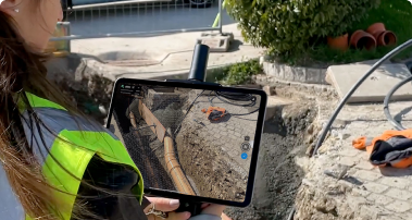
Photogrammetry is the process of measuring with images. These can be images captured with a wide range of devices, including drones, planes, and handheld cameras, to name a few. These images are used to generate accurate and precise 2D and 3D models. Numerous industries can take advantage of those reconstructions, ranging from public safety to industrial inspections to agriculture.
The theories and concepts behind photogrammetry can seem complex at first, which is why we’ve created a list of the top 10 things we think you should know for when you use photogrammetry. They are:
- Geometry
- Radiometry
- Triangulation
- Internal & external parameters
- Initial and computed parameters
- RTK & PPK
- Coordinate system
- Tie points
- Ground Sampling Distance
- Volume measurement
With this list, you can grasp the basic ideas behind photogrammetry, understand how the technology works, and be ready to apply it in your own field!
Geometry
Geometry is a set of characteristics we use to define the size, shape, orientation, and position of something. This information can be reconstructed and analyzed with photogrammetry software. So how does that work? A photograph captures“colinearity”. Colinearity, at a basic level, means that at least three points appear on the same line. With photogrammetry, we consider that line to be a ray of light. So three fundamental points will be on this ray of light, or line: an object, the point the camera focuses on, and the image of that object on the camera’s sensor.
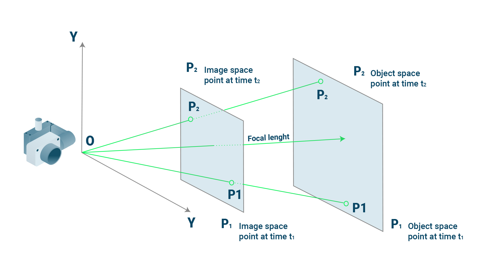
Now, with the right software, you can interpret how the points that intersect a ray of light are part of a bigger scene that was captured by the camera. The length and angle of the “line” is affected by the camera’s exact location when the photos were taken. Photogrammetry software analyzes the behavior of light and colinear elements to recreate the geometry of the scene. To simplify: our photogrammetry software (PIX4Dmapper, PIX4Dfields, PIX4Dmatic, PIX4Dcloud, PIX4Dinspect) will use data from the camera and the photos themselves to generate a geometrically accurate reconstruction of a project area.
Radiometry
Radiometry is a method for analyzing electromagnetic radiation. It is a way to measure how light interacts with different objects, including wavelengths of energy that are not visible to the human eye. So what does that have to do with photogrammetry?
Whenever you look at an object, you see light of specific colors reflected back at you. There are more colors than you can see - we only perceive what our eyes can detect. For example, when you look at plants, you’re usually going to see a predominance of green. Green light is reflected by plants because they do not use it when they absorb energy from the sun. With radiometry, you can measure how plants reflect that light - as well as the quantities and variations of light that we cannot see with the naked eye.
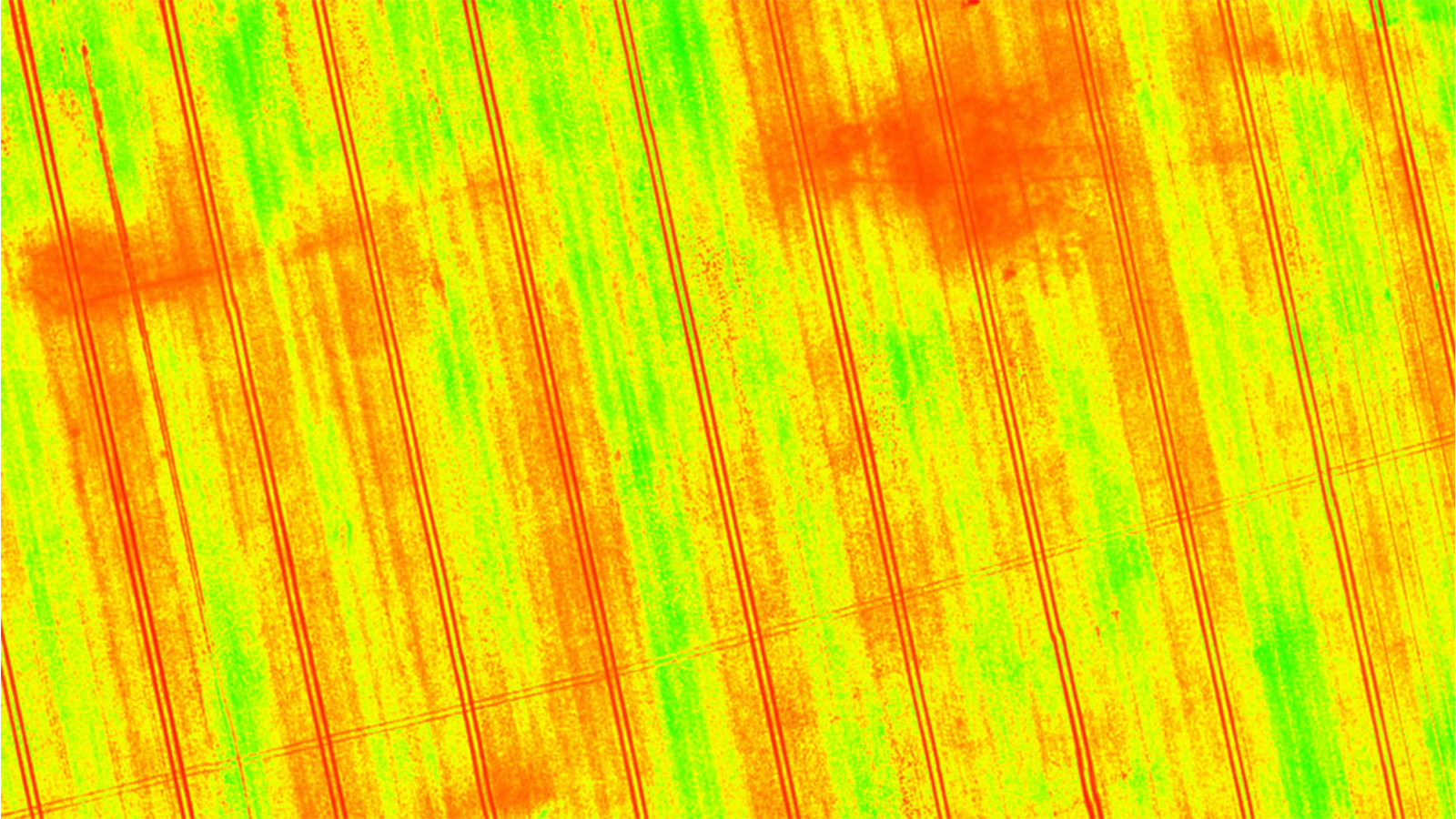
To use radiometry in photogrammetry, you can use specific sensors and cameras that pick up near-infrared light, also known as a multispectral sensor. These cameras analyze light differently from a standard RGB (Red-green-blue) camera. The data from those specialized cameras can be used for agricultural photogrammetry. If you run that data through specialized formulas, you can create a vegetation index. This is a 2D map of a crop or field that analyzes how plants reflect light. The way that a plant reflects light will tell you about its health, growth stage, and whether it is under stress before you can see it with your own eyes. Thanks to this method of using drones and remote sensing, growers can use photogrammetry to learn more about their crop than is visible to the human eye.
Triangulation
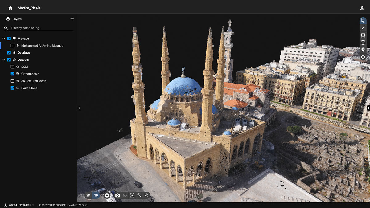
The photos collected for photogrammetry are 2D, and for many outputs - like digital surface models or point clouds - we need to convert that data to be usable in 3D. Triangulation is the technique for creating 3D point measurements.
Triangulation is also used by our eyes. The idea is that images taken from different locations can be used to create a 3D model by comparing the differences between them. Each photo represents a different line of sight, and these can be corroborated with other photos to find intersections between points. As we saw with colinearity and Geometry, you can use this data to measure distances, and by adding overlap between multiple photos, you can use triangulation to create a 3D model. As a result, the Pix4D Support team recommends you gather photos with the appropriate amount of overlap to ensure you have enough data to create a 3D model that is accurate and has no gaps.
Internal & external parameters
We’ve covered the basic science behind how we can convert photos into 2D and 3D models. To take advantage of this technology, you need to have an appropriate photogrammetry data collection tool like a drone or camera.
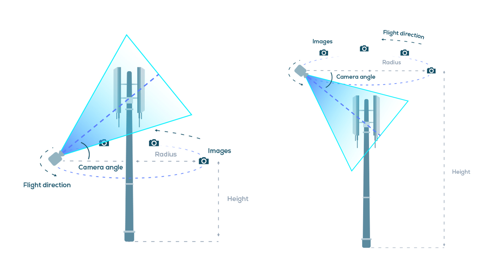
Every camera has certain capabilities within its design. These specifications affect how the camera works - for instance, whether or not it has a rolling shutter. The parameters include:
- Internal camera lens
- Position of the camera projection center
- The rotation matrix that defines the camera orientation
Some of these parameters are internal to the camera (for instance, the camera’s lens) whereas others are external, like the position of the camera when photos are taken. When processing photos with photogrammetry software, these parameters need to be defined to make sure they are taken into account during processing. This ensures accuracy in the outputs as the software will tailor its processing settings to match the camera used.
Initial and computed parameters
To make sure we can generate accurate reconstructions we need some basic information about the equipment used to reconstruct the scene: the camera (and, if relevant, the drone). The camera can be defined by two sets of parameters. Firstly, the internal parameters, are to do with the geometry of the camera itself. The way that the camera interprets light is specific to the camera and affects the processing of images for a 3D reconstruction. On the other hand, the external parameters define the position and orientation of the camera when it captured the photos.
In an ideal world, that information would be available to us from the moment an image is captured through metadata, but it is not always accurate. As a result, specialized photogrammetry software will gather all of the initial parameters of a project before processing.
The software will then optimize those parameters, or compute a set of parameters that more accurately represent the camera’s geometry, position, and orientation. They are changed from the initial parameters to the computed ones. These changes will ensure the accuracy of a project. The more accurate a project is, the more applications it can be used for. If a 3D model is accurate to within a few centimeters, it can reach industry standards as defined by certification bodies, such as Bureau Veritas, and be used for major construction or surveying projects, or even in legal investigations for accidents and crime scene reconstruction.
RTK & PPK
We’ve mentioned “accuracy” a few times already. Accuracy is one of the major concerns of photogrammetry: how do you make sure that the 3D model you have created is true to reality? There are several methods for this, and they rely on accurate geolocation - being able to pinpoint exactly where you are on earth.
RTK (real-time kinematic) and PPK (post-processing kinematic) are methods for measuring and recording geolocational data. They are both GPS correction technologies that collect location data, identify errors, and make corrections either during or after surveying.
RTK takes place during a survey or drone flight. A drone or data collection tool, like the viDoc RTK Rover, will have a GNSS RTK receiver that gathers data from satellites and connects to a local base station or network to gather geolocational information during image capture. This data is tagged onto the photos. The camera positions are calculated in real-time with reference to a local base station. The calculations are used to correct the camera position if it is not accurately recorded, which helps bring the accuracy to within two or three centimeters horizontally and vertically.
PPK works by being completed after data collection and can be used in the absence of hardware with RTK capabilities. The drone writes geocoordinates onto each image based on the drone’s onboard GNSS receiver. At the same time, a base unit (such as a CORS network or GNSS base station) will also record positional information. This data is used to determine geolocation points and references. PPK can be used if RTK is not an option or there are no tie points available, such as in fast-mapping missions or disaster recovery drone missions.
Both of these techniques serve the common purpose of ensuring the accuracy of a project by keeping it accurate to within centimeters (if done correctly). There is some debate about whether PPK or RTK is better, and it is typically project dependent. Whichever one you use, these will help you to create professional results that can be used for real-world applications such as surveying or monitoring terrain.
Coordinate systems
A coordinate system is a way of organizing reference lines or curves to define locations in space. There are different coordinate systems used around the world as some countries have their own.
A person using photogrammetry processing software needs to define what coordinate system they are using before processing their data. Otherwise, the software could interpret the geolocation data incorrectly and render inaccurate measurements or even distort the final outputs.
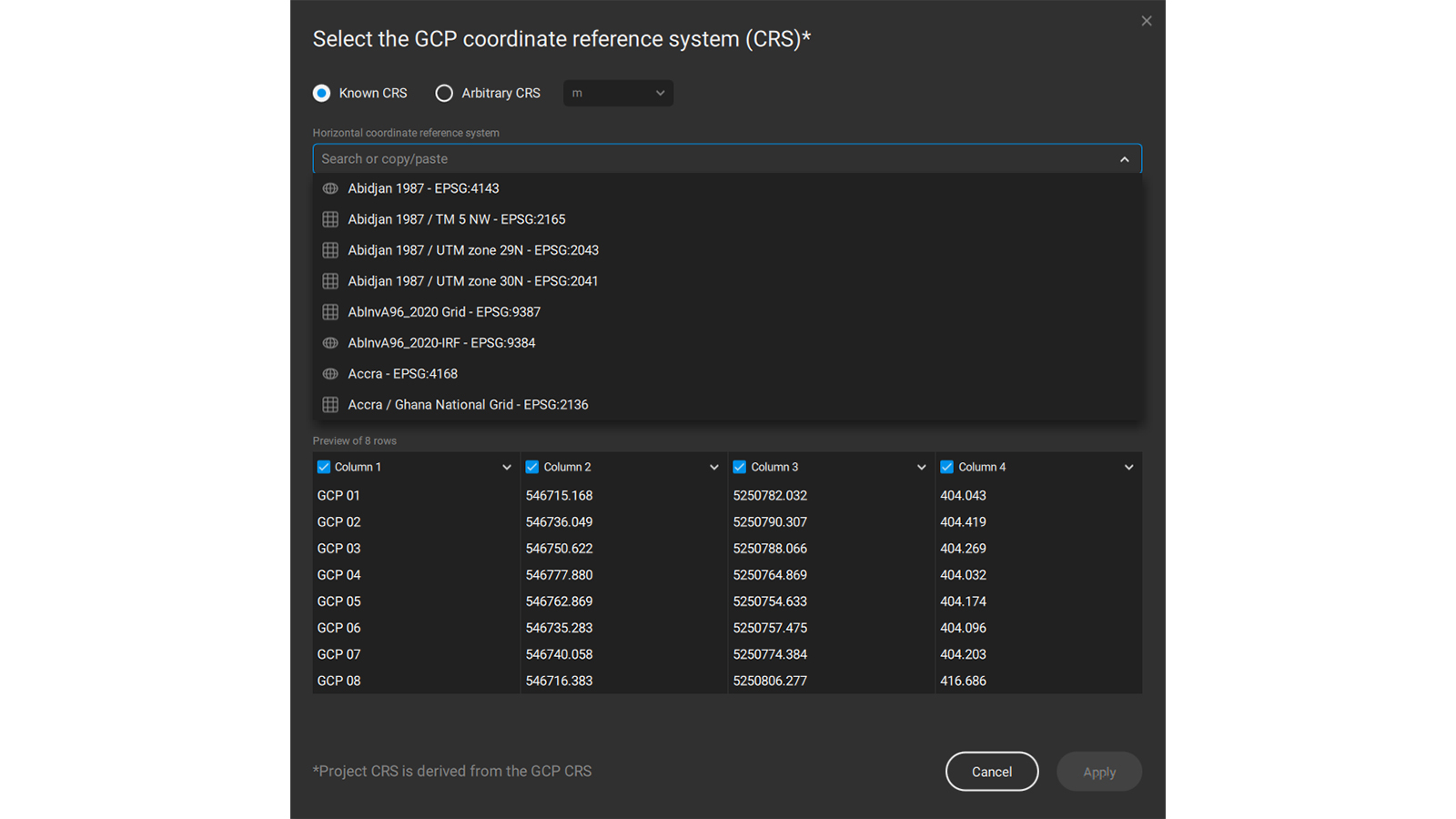
Different coordinate systems will yield slightly different results after processing because of variations between systems. This is why it is important to know what coordinate system you are using when gathering data so it can be defined in the software during processing and give you results that correctly show where you are - rather than mistaking your project site for somewhere completely different!
Tie points
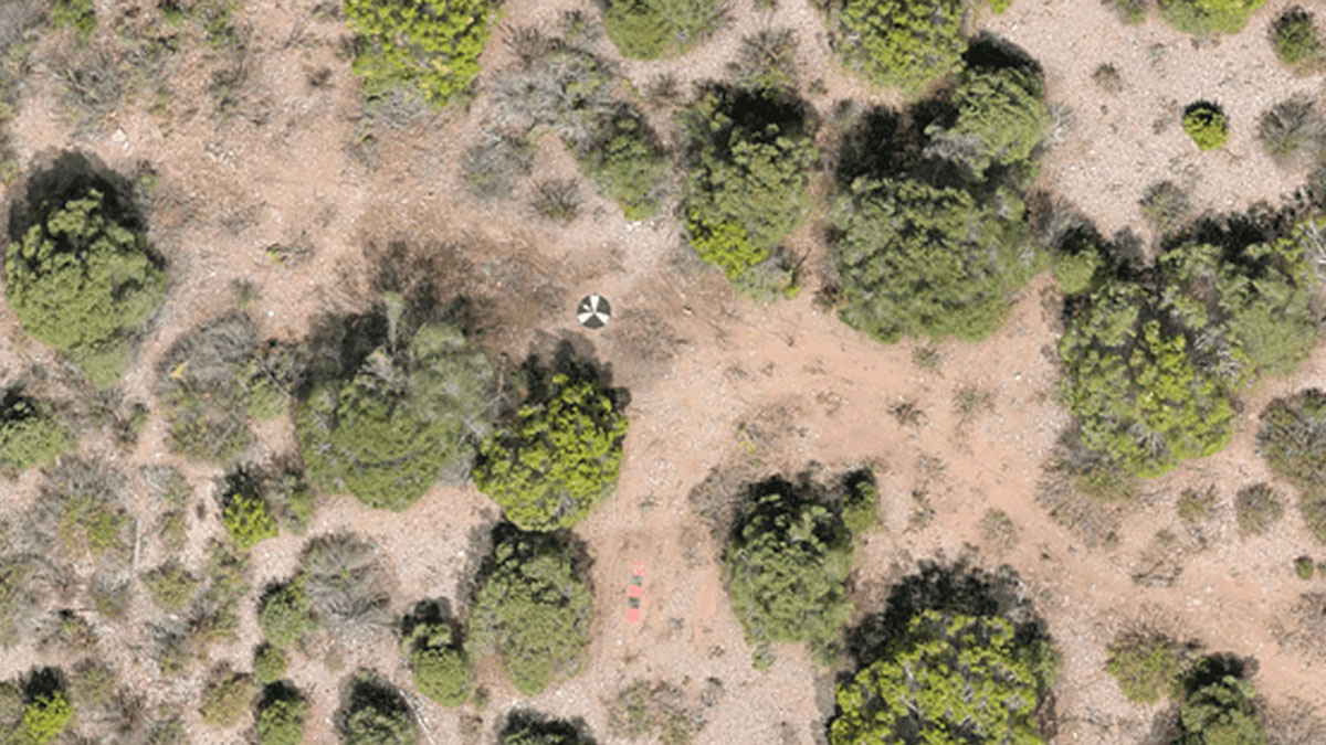
A tie point is a point that is common to several images that can be used to connect them. They are anchor points - a location where the geographic position is absolute. There are several names for tie points (e.g. Ground Control Points or check points).
Ground Control Points, or GCPs, are points with known coordinates. They are precisely measured with an RTK or PPK GNSS receiver - or a similar piece of equipment known as a total station. GCPs are used to accurately locate a project to give you a reconstruction that is true to reality.
Checkpoints are like GCPs, but they do not georeference a project. Instead, they are used to assess the geometric accuracy of the project.
With GCPs and checkpoints, a surveyor can be sure that their photogrammetry outputs are correctly geolocated and measurements made from the 2D or 3D model will be accurate.
Ground Sampling Distance
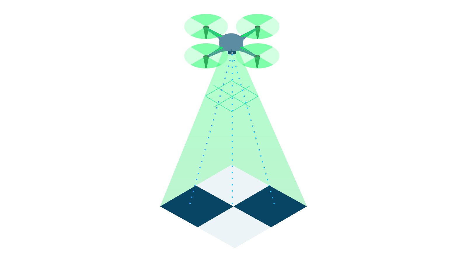
In the continued theme of accuracy comes ground sampling distance, or GSD. GSD is the distance between two adjacent pixel centers measured on the ground. It’s how we relate distances on-screen to distances in reality.
The bigger the GSD value, the lower the spatial resolution of the image. This means you have fewer details.
This is fine if you’re surveying a massive landscape and want to get a general overview of an area. However, if you’re looking for finer elements for a crash investigation or detailed topography, you might want a smaller GSD to be able to search in the model more comprehensively.
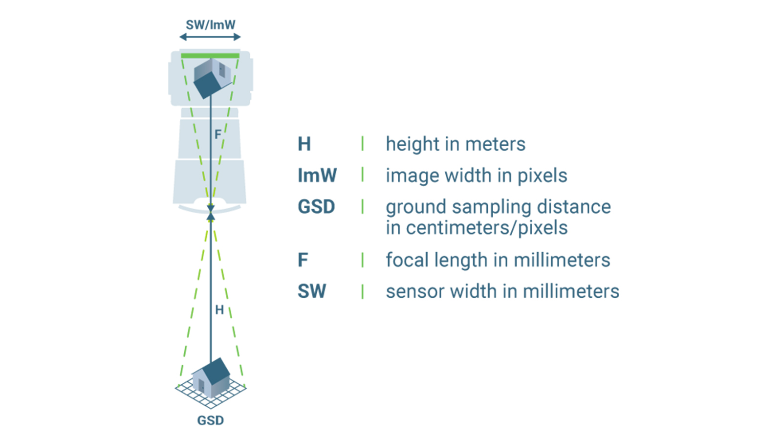
GSD is determined by the flight height and the camera specifications, including the image width, the sensor width, and the focal length. A GSD of 5 cm means that one pixel on the image represents 5cm on the ground in a linear manner (meaning it shows 25 square centimeters). A GSD of 30 cm means that one pixel is equal to to 900 square centimeters (or 30 x 30 cm). The difference is massive. A smaller GSD can be achieved through flying closer to the ground - but will result in a larger dataset and longer processing times. Professional photogrammetrists will adapt their data collection according to the GSD they want.
Volume measurements
This may be a familiar concept, unlike some of the other ones we’ve listed! It may also be one of the simplest. Volumes can be measured according to the base of an object compared to its height or depth. They can be measured with PIX4Dsurvey, PIX4Dcloud, and PIX4Dmapper. Data can be collected to measure volumes with the viDoc RTK rover or a drone.
Measuring volumes with photogrammetry is used by professionals in construction working on projects involving stockpile management, as well as surveyors or public safety operators who need to analyze terrain. Using photogrammetry to measure stockpiles or volumes will save time and improve safety as it saves the surveyor having to walk on a pile to measure the profile of the material. It cuts out the need for manual, cumbersome equipment and can even be completed with automated drone flights and automatic data uploads to PIX4Dcloud. The whole process results in time and money savings, bringing a direct return on investment from using photogrammetry.
Learning more about the science behind photogrammetry
Congratulations on reading this far! Some of the topics covered in this blog are highly technical and may be unfamiliar if you’re new to the industry. Photogrammetry is one of the most exciting methods of measuring and analyzing data. The good news is that there is help if you need it - our Pix4D knowledge base on our Support site is full of information that informed this article, and our expert Trainers can also provide lessons for people new to photogrammetry and working with Pix4D.
If you’re interested in learning more about photogrammetry and its applications, check out the Pix4D blog to learn more and follow us on LinkedIn to see the latest news and use cases.