An introduction to PIX4Dmatic’s Intersection Tie Points
In photogrammetry, tie points are part of how we convert images into 2D and 3D maps. A tie point is an object or point that is identified across images that overlap. Photogrammetry software can recognize these points across photos and use them to reconstruct a scene thanks to image matching. This in turn helps ensure the geometric accuracy of photogrammetry projects.
There are several different forms of tie points in photogrammetry, including ground control points (GCPs), checkpoints (CPs), manual tie points (MTPs), and automatic tie points (ATPs).
PIX4Dmatic, a photogrammetry software dedicated to large-scale aerial and terrestrial mapping, has a unique set of tie points called “intersection tie points” (ITPs).
What are ITPs?
An ITP is used within PIX4Dmatic to optimize how interior or urban scenes are recreated. When linear features intersect, the machine learning within PIX4Dmatic will identify and define it as an intersection tie point. This in turn helps calibrate the scene. The difference between this and other tie points is that it looks specifically at intersection points of linear features, such as the corner of a building.
Why were Intersection Tie Points created?
With more and more people using mobile scanning for indoor 3D reconstructions, the PIX4Dmatic team sought to find ways to optimize calibration of interior scenes. This was the driver behind creating ITPs. These tie points follow human vision and can be created automatically or manually, which provides more control over the data. Because of this, they can then be considered more accurate than traditional ATPs because of how they are made.
With ITPs, 3D reconstructions can be better calibrated - solving the problem the PIX4Dmatic team set out to address. They can be used internally or externally, and are particularly useful for digitizing urban structures.
How are Intersection Tie Points used?
At their base, ITPs improve the calibration of indoor and outdoor scene reconstructions. They are machine-learning objects that use intersecting linear features to generate a tie point. Unlike other tie points, ITPs are intersections that better resemble human thinking, rather than clusters of unique pixels and image texture. The different tie points have differing amounts of influence on the scene’s calibration. Automatic tie points (ATPs) result from an automated keypoint extraction process of unique pixels and image texture. While they are important, they are the least accurate and have the least effect on calibration in PIX4Dmatic.
Intersecting tie points (ITPs) come in two varieties: automatic ITPs (aITPs) and manual ITPs (mITIPs). A machine learning process matches recognizable linear entities within overlapping images. As these are lines that a person would consider, aITPs are considered more trustworthy than the automated keypoint extraction process from ATPs. Thus they have more influence in the calibration process.
For manual intersection tie points, at least two linear features which intersect must be identified in overlapping images. mITPs can be created by converting an aITP to a mITP or by creating a new mITP altogether.
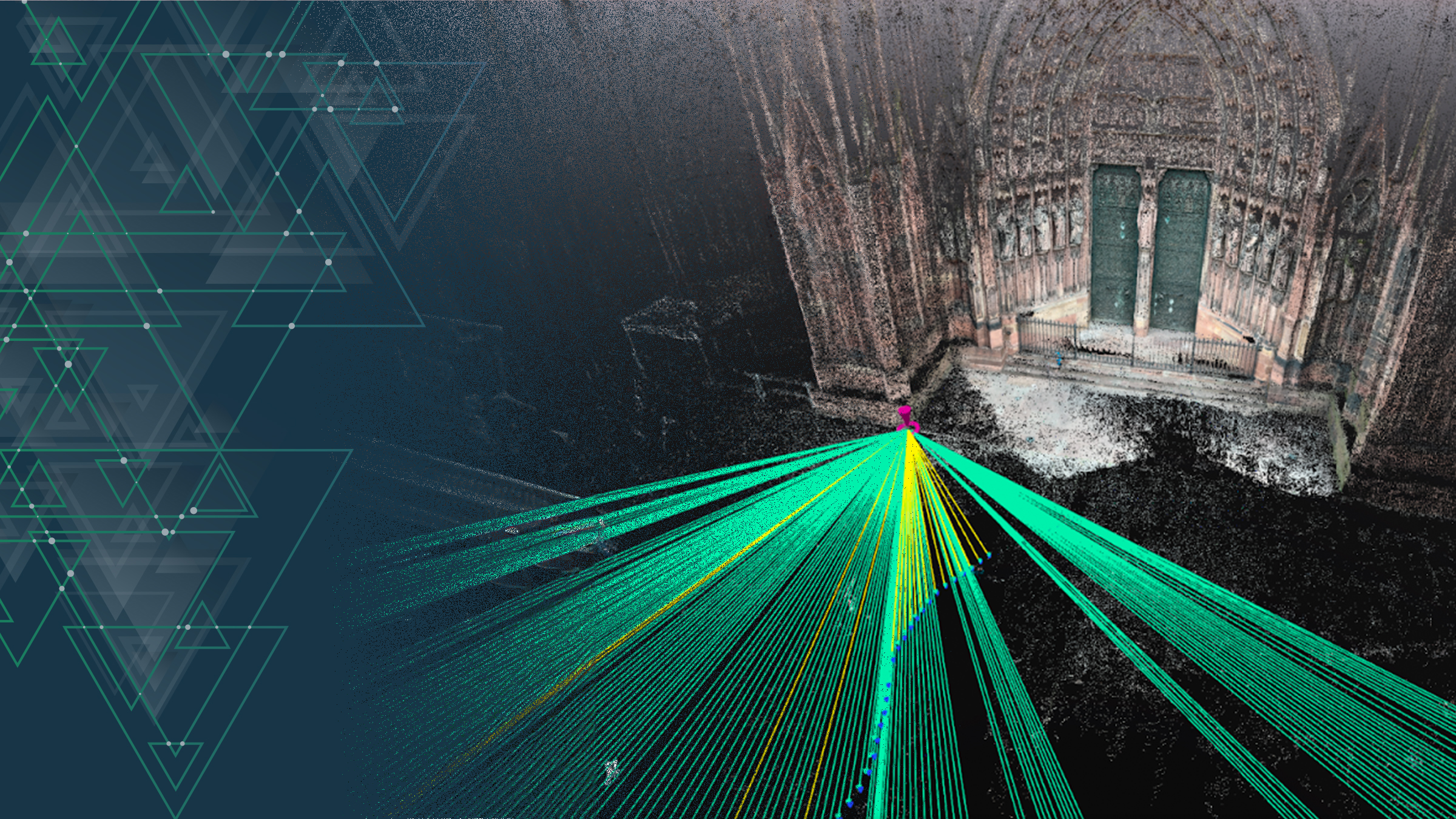
To generate aITPs, PIX4Dmatic users can enable the automatic ITP toggle in the calibration step. Once this toggle is on, linear features that are matched in overlapping images during the image alignment process will be automatically identified.
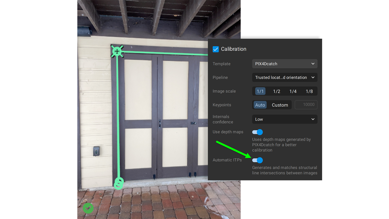
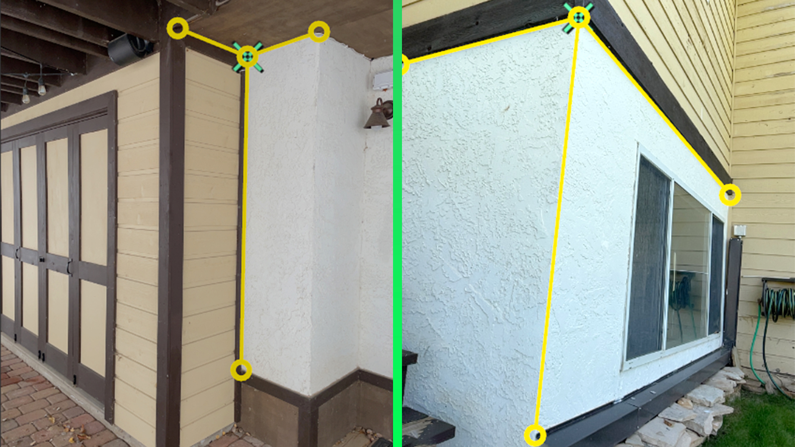
For example, if there are linear features such as a corner of a room, a window, or a door, then PIX4Dmatic will identify them. These automatically generated line segments will appear as green.
To convert an aITP to a mITP open the image viewer in 3D view after calibration when all the aITPs have been generated. Click on the green aITP line segment and it will change to yellow, converting the aITP to a mITP.
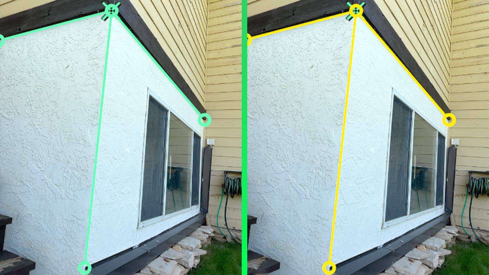
This will give the tie point more influence during re-optimization
Where will ITPs be used?
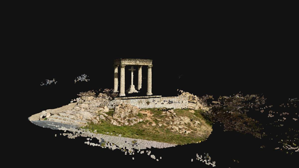
Some examples of when ITPs can be used are: interior design, renovation works, digital twins of industrial buildings, and cultural heritage projects.
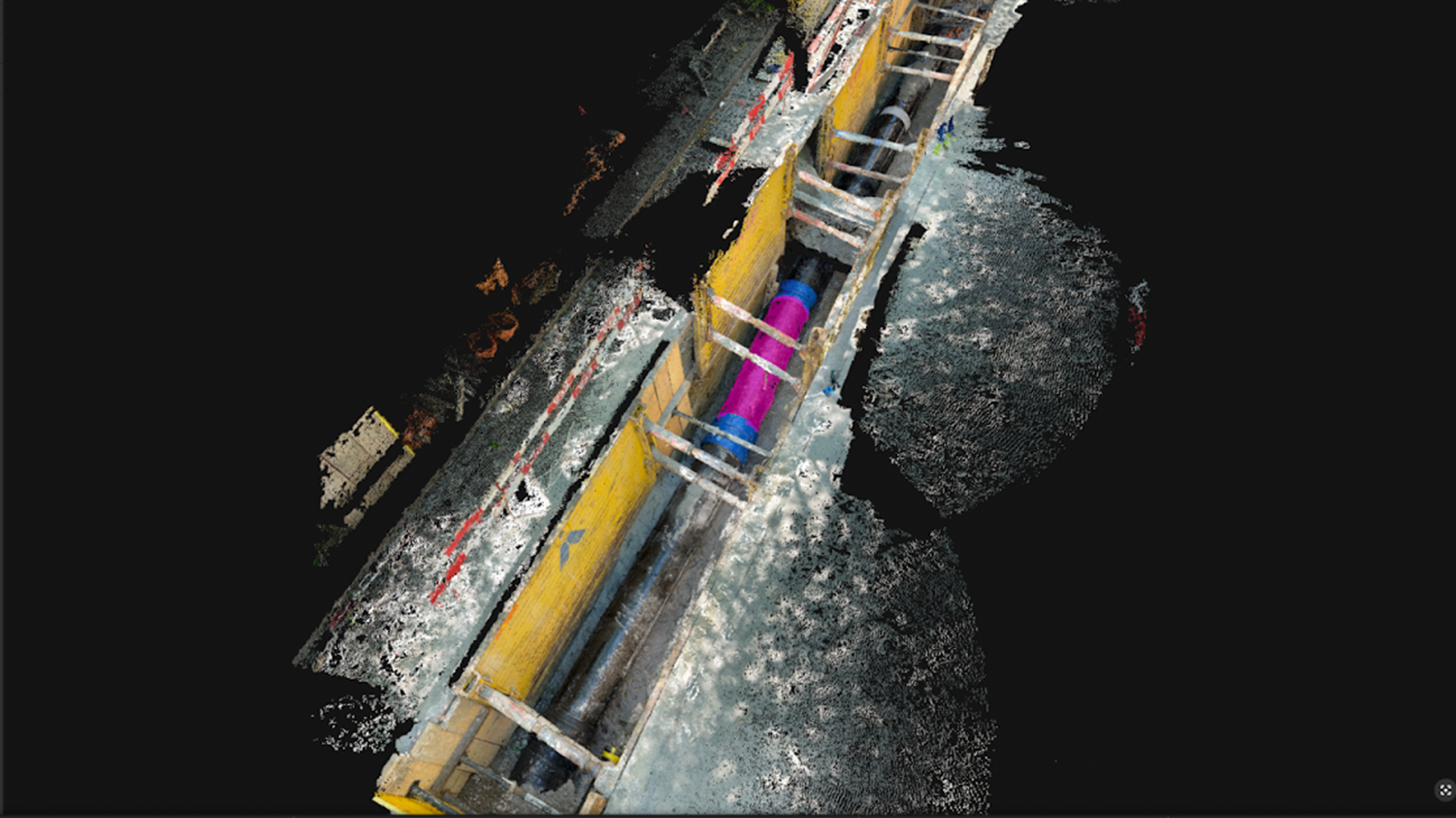
For instance, a person could create an indoor scan of a room to inspect pipes or check on construction plans are on track. The digitized version of the room could be processed with PIX4Dmatic. As internal spaces can have different lighting conditions to outside, the ITPs can help prevent distortion or warping in the 3D model.
As the use and practices of digital scanning indoors and outdoors continue to grow, ITPs will help guarantee the accuracy of projects regardless of their location.
Got questions, or want to get involved? Join the conversation on LinkedIn and follow our hashtag #Pix4DLabs